An anemometer is a device that measures wind speed and direction, playing a crucial role in weather forecasting. Derived from the Greek words ‘anemos’ (wind) and ‘metron’ (measure), this instrument has been a staple in weather stations for centuries. Interestingly, the first known description of an anemometer dates back to 1450 by Italian polymath Leon Battista Alberti.
The anemometer has undergone minimal changes since its 15th-century development. Leon Battista Alberti is credited with inventing it around 1450, although others, like Robert Hooke, developed their own versions. Key improvements include Thomas Romney Robinson’s four-cup design in 1846, John Patterson’s three-cup anemometer in 1926, and enhancements by Brevoort and Joiner in 1935. Later innovations include Derek Weston’s addition of wind direction measurement in 1991 and Andreas Pflitsch’s development of the sonic anemometer in 1994.
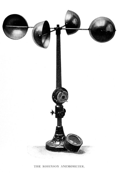
A simple anemometer was invented in 1845 by Rev. Dr. John Thomas Romney Robinson, featuring four hemispherical cups on horizontal arms mounted on a vertical shaft. As wind flowed past the cups, the shaft rotated at a rate proportional to the wind speed, allowing for measurement of average wind speed over time by counting revolutions. This design is known as a rotational anemometer.

A four-cup anemometer works by utilizing the difference in drag coefficients between the hollow and spherical sides of the cups. With a drag coefficient of 1.42 on the hollow side and 0.38 on the spherical side, the cup presenting its hollow side to the wind experiences more force, generating torque and causing the anemometer to spin. This design enables accurate measurement of wind speed.
Theoretically, an anemometer’s rotation speed should be proportional to wind speed. However, factors like turbulence, drag, and friction affect accuracy. Initially, Robinson claimed the cups moved at one-third of wind speed, but this was later found to be incorrect. The anemometer factor, dependent on cup and arm dimensions, can range from 2 to over 3, requiring previous experiments to be repeated to ensure accuracy.
The three-cup anemometer, developed by John Patterson in 1926 and improved by Brevoort & Joiner in 1935, features a nearly linear response with an error of less than 3% up to 60 mph (97 km/h). Each cup produces maximum torque at 45° to wind flow. The design offers more constant torque and faster response to gusts compared to four-cup anemometers.
In 1991, Dr. Derek Weston modified the three-cup anemometer to measure wind direction by adding a tag to one cup. This design change causes cyclical speed variations, allowing wind direction calculation. Wind speed is determined from average cupwheel speed. Three-cup anemometers are now the industry standard for wind resource assessment.
Vane anemometers, also known as windmill or propeller anemometers, measure wind speed with a rotating propeller or vane. Their axis of rotation is horizontal and parallel to the wind direction, requiring a wind vane or similar mechanism to track changes in wind direction.
A vane anemometer combines a propeller and tail on the same axis, providing accurate wind speed and direction measurements. The fan’s speed is measured by a revolution counter and converted to wind speed by an electronic chip, allowing calculation of volumetric flow rate if the cross-sectional area is known. In applications with consistent airflow direction, such as mine and building ventilation, wind vanes (air meters) provide reliable results.
Hot-wire anemometers
Ultrasonic Anemometers
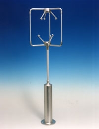
Ultrasonic anemometers, first developed in the 1950s, use ultrasonic sound waves to measure wind velocity. They measure wind speed based on the time of flight of sonic pulses between pairs of transducers.
The time that a sonic pulse takes to travel from one transducer to its pair is inversely proportionate to the speed of sound in air plus the wind velocity in the same direction:
t = L / (c + v)
where t is the time of flight, L is the distance between transducers, c is the speed of sound in air, and v is the wind velocity. To correct for the speed of sound in air, sound pulses are sent in both directions, and the wind velocity is calculated using the forward and reverse times of flight:
v = 1/2 L (1/t1 – 1/t2)
where t1 is the forward time of flight and t2 is the reverse.
Advantages:
Ultrasonic anemometers have no moving parts, requiring little maintenance, and can operate in harsh environments over a wide range of wind speeds. They can measure rapid changes in wind speed and direction, making them useful for measuring turbulent airflow patterns.
Disadvantages:
The main disadvantage is the distortion of airflow by the structure supporting the transducers, which requires correction based on wind tunnel measurements. Rain or ice on the transducers can also cause inaccuracies.
Additional Applications:
Since the speed of sound varies with temperature, ultrasonic anemometers can also be used as thermometers. Measurements from pairs of transducers can be combined to yield velocity measurements in 1-, 2-, or 3-dimensional flow. Two-dimensional sonic anemometers are used in applications such as weather stations and wind turbines, while three-dimensional sonic anemometers are used to measure gas emissions and ecosystem fluxes.
Ultrasonic Anemometers
Ultrasonic anemometers, first developed in the 1950s, use ultrasonic sound waves to measure wind velocity. They measure wind speed based on the time of flight of sonic pulses between pairs of transducers. The time that a sonic pulse takes to travel from one transducer to its pair is inversely proportionate to the speed of sound in air plus the wind velocity in the same direction: t = L / (c + v) where t is the time of flight, L is the distance between transducers, c is the speed of sound in air, and v is the wind velocity. To correct for the speed of sound in air, sound pulses are sent in both directions, and the wind velocity is calculated using the forward and reverse times of flight: v = 1/2 L (1/t1 – 1/t2) where t1 is the forward time of flight and t2 is the reverse. Advantages: Ultrasonic anemometers have no moving parts, requiring little maintenance, and can operate in harsh environments over a wide range of wind speeds. They can measure rapid changes in wind speed and direction, making them useful for measuring turbulent airflow patterns. Disadvantages: The main disadvantage is the distortion of airflow by the structure supporting the transducers, which requires correction based on wind tunnel measurements. Rain or ice on the transducers can also cause inaccuracies. Additional Applications: Since the speed of sound varies with temperature, ultrasonic anemometers can also be used as thermometers. Measurements from pairs of transducers can be combined to yield velocity measurements in 1-, 2-, or 3-dimensional flow. Two-dimensional sonic anemometers are used in applications such as weather stations and wind turbines, while three-dimensional sonic anemometers are used to measure gas emissions and ecosystem fluxes.
Laser Doppler Anemometers
In laser Doppler velocimetry, laser Doppler anemometers use a beam of light from a laser that is divided into two beams, with one propagated out of the anemometer.
Particulates (or deliberately introduced seed material) flowing along with air molecules near where the beam exits reflect, or backscatter, the light back into a detector, where it is measured relative to the original laser beam. When the particles are in great motion, they produce a Doppler shift for measuring wind speed in the laser light, which is used to calculate the speed of the particles and, therefore, the air around the anemometer.
Laser Doppler Anemometers In laser Doppler velocimetry, laser Doppler anemometers use a beam of light from a laser that is divided into two beams, with one propagated out of the anemometer. Particulates (or deliberately introduced seed material) flowing along with air molecules near where the beam exits reflect, or backscatter, the light back into a detector, where it is measured relative to the original laser beam. When the particles are in great motion, they produce a Doppler shift for measuring wind speed in the laser light, which is used to calculate the speed of the particles, and therefore the air around the anemometer. Laser Doppler Anemometers Laser Doppler anemometers use a laser beam divided into two parts, with one beam exiting the anemometer. Particulates or seed material in the airflow reflect the light back into a detector. The reflected light is measured relative to the original laser beam. The Doppler shift caused by particle motion is used to calculate wind speed and air velocity around the anemometer.
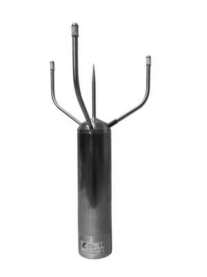
Central spike keeps birds away.
Ultrasonic anemometers
Hot wire anemometers measure air flow by using a fine wire, typically made of tungsten, that’s electrically heated to a temperature above ambient. As air flows past the wire, it cools down, changing its electrical resistance. By monitoring this resistance change, the device can calculate air speed. However, most hot wire anemometers can’t determine airflow direction without a wind vane.
There are several types of hot wire anemometers, including:
Constant Current Anemometer (CCA)
Constant Voltage Anemometer (CVA)
Constant Temperature Anemometer (CTA)
Pulse-Width Modulation (PWM) anemometers, which use pulses of current to heat the wire and measure velocity based on pulse duration.
Hot wire anemometers are extremely sensitive and have high frequency response, making them ideal for studying turbulent flows and rapid velocity fluctuations. However, they’re delicate and prone to damage.
For industrial applications, thermal flow meters are used. These devices have two pins or strings with fine wires that monitor temperature variations, making them more durable and suitable for measuring flow in pipes, ducts, and stacks. They’re often used in dirty environments where classic hot wire anemometers would fail.
: Hot wire anemometers measure air flow by using a fine wire, typically made of tungsten, that’s electrically heated to a temperature above ambient. As air flows past the wire, it cools down, changing its electrical resistance. By monitoring this resistance change, the device can calculate air speed. However, most hot wire anemometers can’t determine airflow direction without a wind vane. There are several types of hot wire anemometers, including: Constant Current Anemometer (CCA) Constant Voltage Anemometer (CVA) Constant Temperature Anemometer (CTA) Pulse-Width Modulation (PWM) anemometers, which use pulses of current to heat the wire and measure velocity based on pulse duration. Hot wire anemometers are extremely sensitive and have high frequency response, making them ideal for studying turbulent flows and rapid velocity fluctuations. However, they’re delicate and prone to damage. For industrial applications, thermal flow meters are used. These devices have two pins or strings with fine wires that monitor temperature variations, making them more durable and suitable for measuring flow in pipes, ducts, and stacks. They’re often used in dirty environments where classic hot wire anemometers would fail.
Acoustic resonance anemometers
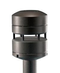
Acoustic Resonance Anemometer
Acoustic resonance anemometers are a recent variant of sonic anemometers. This technology was invented by Savvas Kapartis and patented in 1999. Unlike conventional sonic anemometers, which rely on time-of-flight measurement, acoustic resonance sensors use resonating acoustic (ultrasonic) waves within a small, purpose-built cavity to perform their measurements.
Acoustic Resonance Anemometer Acoustic resonance anemometers are a recent variant of sonic anemometers. This technology was invented by Savvas Kapartis and patented in 1999. Unlike conventional sonic anemometers, which rely on time-of-flight measurement, acoustic resonance sensors use resonating acoustic (ultrasonic) waves within a small, purpose-built cavity to perform their measurements.
Acoustic resonance technology allows measurement within a small cavity, making the sensors typically smaller than other ultrasonic sensors. Their compact size renders them physically robust and easy to heat, enhancing resistance to icing. This feature set enables high data availability, suiting them for wind turbine control and applications requiring compact, durable sensors, such as battlefield meteorology. While measurement accuracy may be a concern compared to calibrated mechanical sensors, the longevity and lack of required recalibration often offset this limitation for many applications.
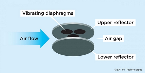
Built into the cavity is an array of ultrasonic transducers, which create separate standing-wave patterns at ultrasonic frequencies. As wind passes through the cavity, it induces a phase shift in the waves. By measuring this phase shift in the received signals and processing the data mathematically, the sensor provides an accurate horizontal measurement of wind speed and direction. Acoustic resonance technology allows measurement within a small cavity, making the sensors typically smaller than other ultrasonic sensors. Their compact size renders them physically robust and easy to heat, enhancing resistance to icing. This feature set enables high data availability, suiting them for wind turbine control and applications requiring compact, durable sensors, such as battlefield meteorology. While measurement accuracy may be a concern compared to calibrated mechanical sensors, the longevity and lack of required recalibration often offset this limitation for many applications.

💬 COMMENT